How to Read Construction Drawings & Set-up Bids for Success
Written by Luis Acuna
Introduction
There are numerous ways to ensure a construction project is unsuccessful. One of the easiest ways in the construction industry to ensure a project’s failure starts at the beginning of the project, prior to contract award, during the bidding phase.
During the bidding phase, estimators working for the subcontractors and general contractors are tasked with reading construction blueprints, identifying scope, and mitigating risks by interpreting the drawings and collating costs into completed bids. As such, a metric for gauging an estimator’s worth can be their ability to read drawings.
In this article, we will provide an overview of how to read construction drawings and review how estimators can set up bids for success.
What Are Construction Drawings?
Construction drawings are plans created by architects and engineers that inform the general contractor what type of project is being requested of the client, A.K.A the Owner.
Construction drawings will provide information such as the project's square footage, what type of material should be used and where, how many floors/rooms shall be constructed, etc.
Regarding what needs to be built, construction drawings will provide information to the general contractor but will not dictate how the project shall be built. Sequencing and use of different construction techniques are the general contractor’s responsibility, which are also known as “means and methods”
The term construction drawings are synonymous with the following terms:
- Plans
- Drawings
- Blueprints
This is a dated term that was used when drawings were physically created on blue paper for easy copying.
Why Are Construction Drawings Important?
Construction drawings are important because they provide direction, vision, and information from the owners, architects, and engineers to the general contractor. Construction drawings are contractual documents that answer the following questions for the general contractor:
- What type of project is being constructed?
- What will be the main use of the project?
- Where is the building located?
- What types of codes govern the project?
- How many floors are there?
- What is the area (sf) of the project?
- How many rooms are in the project?
- What type of material should be used in the project?
The Components of Construction Drawings
There are countless articles online that guide how to read construction drawings. However, I believe your time is better spent reviewing the actual drawings vs. reading general guides online. Below is a detailed description of the elements found in construction drawings:
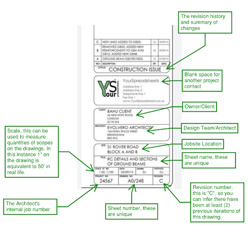
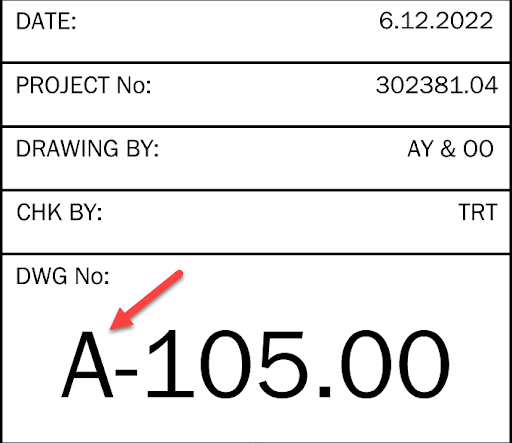
Title Block:
Title blocks are a section of the drawings that provide administrative data regarding the project such as the client, design team, sheet number, sheet title, etc.
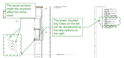
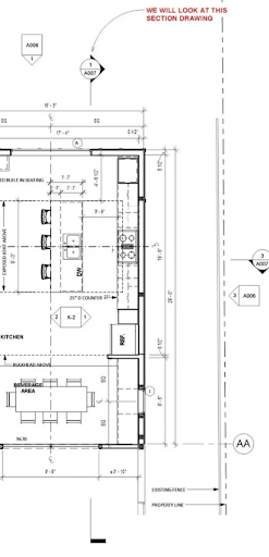
Key Notes:
Keynotes are typically a series of numbers representing the scope the designer wants to draw attention to without creating an unnecessary drawing.
In the example below, the designer states that keynote 7 informs the general contractor that the entire floor shall be removed from the concrete slab, meaning any existing wood flooring, tile, or carpet should be removed until the concrete structure is reached.
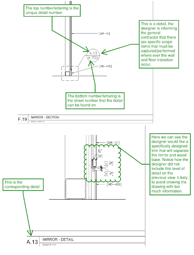
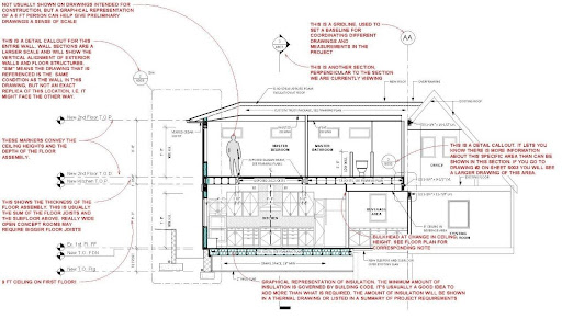
Details:
Details are enlarged drawings of specific parts of the construction project. They provide a more in-depth view of how different components are constructed or installed. Details are used to inform the general contractor of specific scope, they are often used for precise intricacies and provide an additional layer of information.
Plan Legend:
The plan legend explains the symbols and abbreviations used throughout the construction drawings. Since drawings are a graphical representation, a variety of symbols are used to represent physical elements (like doors, windows, electrical outlets) and abstract concepts (like property lines or north direction).
Drawing Scale:
The drawing scale indicates the relationship between the dimensions in the drawing and the actual dimensions of the physical space. Understanding the scale is crucial for accurately interpreting the sizes and distances in the drawing.
Orientation:
Orientation refers to the direction that the building or structure faces. It's often indicated by a north arrow on the plans. This helps in understanding the positioning of the building in relation to its surroundings, which is important for factors like sunlight exposure and wind direction.
Elevations:
Elevations are typically exterior views of what the finished project will look like. They occasionally include additional details and are differentiated by N/E/S/W or Front, Back, Left, Right.
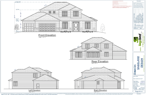
Sections
Sections are typically cross-sectional views of the project which span the entire height or width of a particular area of the project. Sections are helpful since they tie-in multiple rooms, transitions, and details to provide a wholistic view of the project.
Below are great examples from the Mangan group:
Step-by-Step Guide to Setting Up Bids For Success
Below is a list of steps we will review in detail.
- Organizing the bid files
- Identifying the knowns & unknowns
- Page turns & Research
- Reviewing the Detail & General Note Sheets
Step 1: Organizing Bid Files (Document Control)
Organizing the bid files, a.k.a “Document Control”, is paramount; failing to include specific drawing sets or reports can be the deciding factor in winning a bid. Maintaining a clean and concise record of all documents that the client has transmitted will assist in risk mitigation. A typical document control structure may include drawings, specifications, contracts, reports, and addendums. We will review a methodology for organizing drawings specifically. Drawings can be categorized by their discipline; most projects will consist of the following:
- General
- Shoring
- Demolition
- Architectural
- Structural drawings
- Civil
- Mechanical
- Plumbing
- Electrical
- Fire Protection
- Interior Design
Here is an example of a sheet index and the different disciplines that are included in a set of drawings.
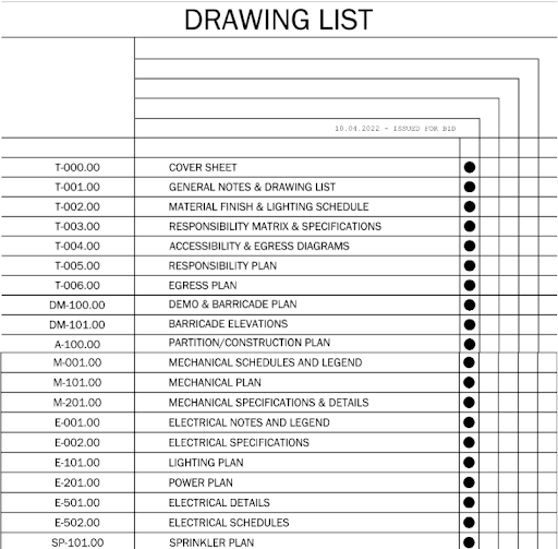
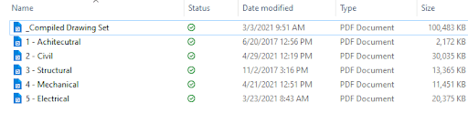
Based on this drawing list we know the following disciplines are included based on the sheet number
- T - General
- DM - Demolition
- A - Architectural
- M - Mechanical
- E – Electrical
- SP – Fire Protection
Drawings can be identified by the sheet number of the title block. This is an architectural drawing, identified by the “A” prefix.
Assuming the client sent the drawings as a single pdf, one organization strategy would be to separate all the disciplines into separate files in addition to the original file transmitted by the client. Here is a quick guide on how to create separate files utilizing Bluebeam:
Here is an example of how pdfs can be organized upon receipt of drawings.
This type of file organization is helpful to divide on conquer when estimating large projects that require multiple estimators.
Step 2: Identifying the Knowns & Unknowns
Once the files have been separated, we will have a clear understanding of what drawings were shared by the client. This is important as the inclusion or exclusion of specific disciplines can lead to additional information, below are a few examples:
- If the client provided Architectural, Structural, Civil, & MEPF drawings but did not include any interior design drawings, it may mean that the interior design is incomplete or that the client may be looking to bid the T.I scope in a separate contract.
- If the client only provided Architectural, Structural, and Civil drawings, it is possible that the client would like the MEPF trades to be design-build.
Organizing the drawings will assist the estimator in establishing what is being asked of by the client. It will also mitigate risks for both the client and general contractor if the client mistakenly forgot to share a certain drawing, spec, or report that they would like included in the contract.
Step 3: Page Turn & Research
At this stage of the process, we can begin what is called a page turn. It is literal as it sounds. Flip through every page of the drawings, and try to cover as much ground as possible without getting stuck on one sheet for too long, and keep a running list of questions to refer too once complete. Architectural drawings provide a strong starting point, specifically the cover page since it typically includes general project information such as:
- Who is client
- Who comprises the design team?
- Where is the project located?
- What is the scope of work? (This is often a general description of what was included in the building permit.)
- What codes are relevant to this project?
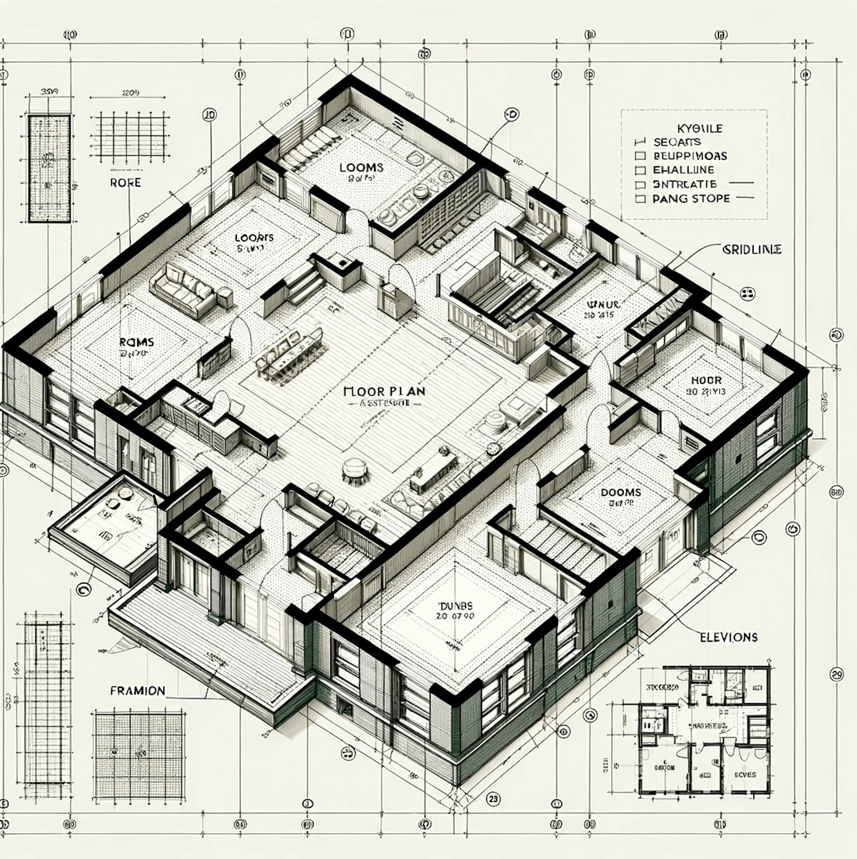
Following the coversheet, review each floor plans provided, floor construction plans typically identify the following:
- What is the purpose of the floor in question?
- How many doors will be required?
- Are there gridlines on this project?
- How much drywall/framing scope is on the specific floor?
- What portion of the building is existing?
Other items of importance on floor plans include keynotes, sections, elevations, and enlarged construction plans. Reviewing each floor plan can be time consuming but will ultimately be worth the effort. If there are terms, abbreviations, or notes that do not make sense, creating a running list of questions would be helpful. The questions can then be answered by the owner or researched individually, in the even that neither outcome provides an answer, a qualification can be made.
Reviewing the floor construction plans should lead to the review of all other pertinent elevation, section, and detail drawings.
Repeat this process for every page of all the drawing disciplines shared by the client.
One suggestion for deciding the order of what drawings to review would be to mimic the project schedule. Review the drawing disciplines in the same order that the project would physically progress. If a project schedule does not exist, below is a general sequence for a ground-up construction project:
- Demolition
- Excavation/Shoring
- Structural Engineering Plans
- Architectural
- MEPF
- Interior
Step 4: Review the Detail & General Note Sheets
Lastly, after the page turn has been completed, an additional review of each detail/general note sheet should be performed. When it comes to construction drawings, one quote that comes to mind is “The devil is in the details”. An opportunistic estimator would view these as the areas for the greatest amount of risk mitigation.
Typical details and general notes hold a significant amount of risk because they are often all encompassing, and they may not be referenced on floor plans, elevations, or sections. A helpful exercise would be highlighting each detail/general note and identifying a subcontractor or line item in the bid that will cover the scope in question.
Below are handful of examples:
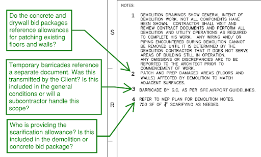
Here is an example of a typical keynote section for demolition drawings. One might assume that the demolition drawings would only include demolition scope, however review of the keynotes reveal temporary barricading, concrete, and drywall scope.
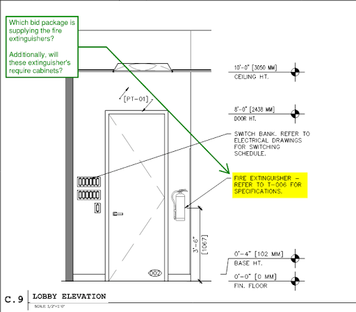
Here is an example of a drywall scope that is located on an electrical drawing.
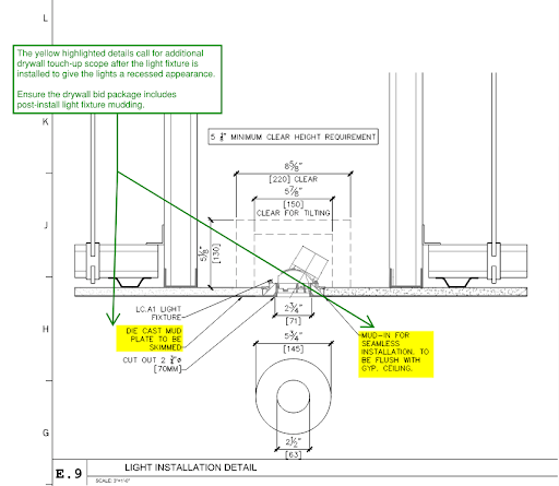
Here is an example of drywall or specialty scope located on an interior drawing.
Closing Notes
To recap, reading and interpreting construction drawings accurately is critical for developing precise bids and avoiding costly mistakes. We reviewed key components of drawings and a systematic process for reviewing plans:
- Organize all bid documents for easy reference and ensure nothing is missing. Having all relevant information in one place aids understanding.
- Note what disciplines are covered in the drawings as a guide for identifying potential scope gaps or areas that require design-build.
- Conduct thorough page turns of all drawings to understand scope and generate questions on unclear items. Review drawings in a logical sequence following the construction process.
- Pay special attention to details, general notes, legends etc. as these often contain hidden scope not shown elsewhere. Highlight these items and tie them back to your bid.
Adopting disciplined processes for reading and analyzing plans, along with effective organization and thoroughness, enables you to develop accurate, competitive bids. Missing steps can lead to flawed assumptions and unwanted surprises that will throw your bid off.
I'd encourage you to leverage checklists and templates to standardize your personal approach across projects. With practice, your individual skills at reading drawings and estimating will improve dramatically. Before you know it, you'll be able to whip up bids more efficiently than ever. Stick with the systematic methods outlined here and you'll become an expert estimator in no time! Let me know if you have any other questions as you hone your skills.